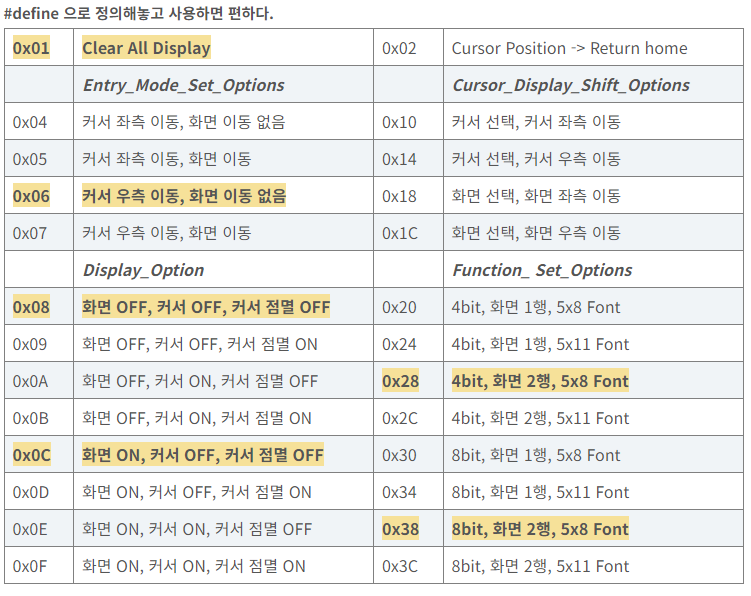
[UART - Interrupt]
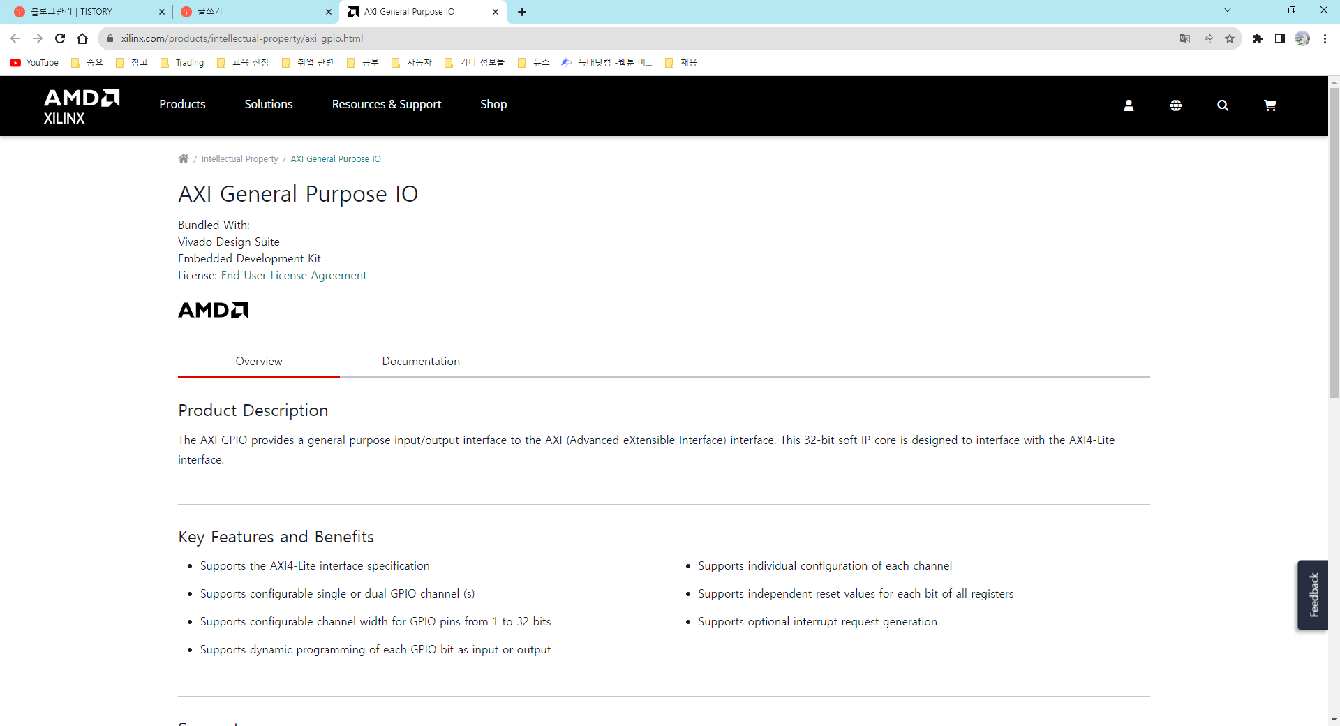
📌 Document
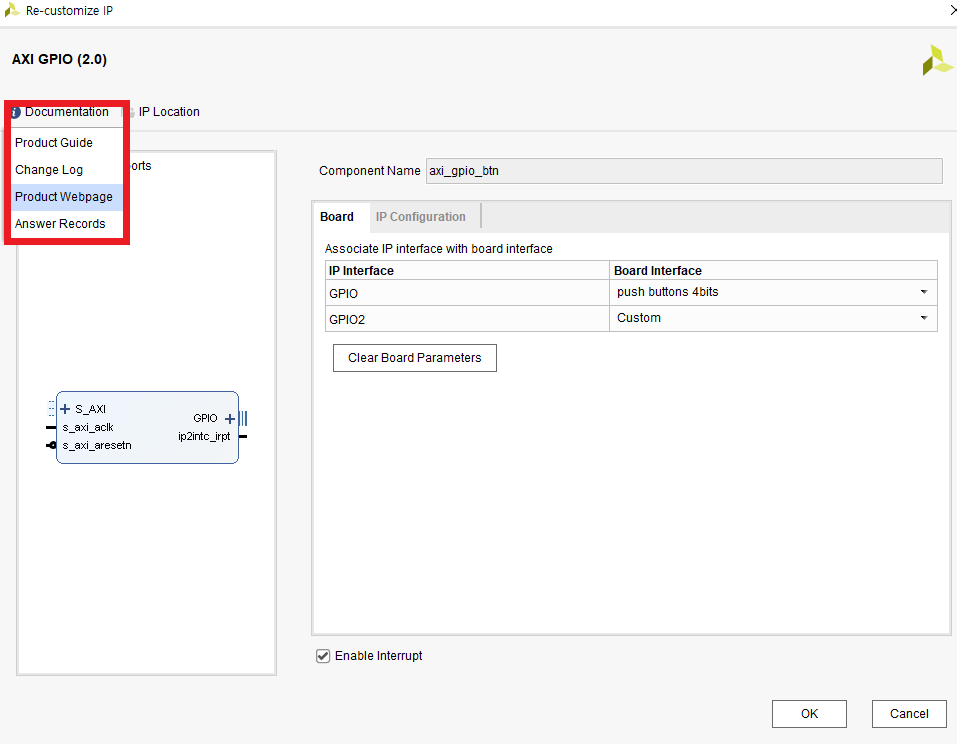
Pmod
: 보드만드는 회사의 규격, 표준은 아님.
인터럽트를 배웠으니, 이제 UART를 활용해서 수신을 할 수 있다.
인터럽트 없이도 가능하긴 한데, 계속 입력받을 수는 없으니까~
필요할 때만 받도록 만들어 보자.
📌 Main Code
전에 만들었던 btn_intc_hw를 가져오자.
#include <stdio.h>          // 표준 입력/출력 함수
#include "platform.h"       // 플랫폼에 특화된 정의 및 초기화
#include "xil_printf.h"      // Xilinx printf 함수
#include "xparameters.h"     // 하드웨어 플랫폼의 매개변수 정의
#include "xgpio.h"           // 하드웨어용 일반 I/O 함수
#include "xintc.h"           // 인터럽트 컨트롤러 함수
#include "xil_exception.h"
#include "xuartlite.h" // UART를 위한 헤어파일

//////////////////////// User Define ////////////////////////
#define BTN_ID XPAR_AXI_GPIO_BTN_DEVICE_ID  // 버튼용 GPIO 컨트롤러의 ID
#define BTN_CHANNEL 1                        // 버튼용 GPIO 채널
#define BTN_MASK 0b1111                      // 버튼에 대한 마스크, 하위 4비트만 사용

#define UART_ID XPAR_UARTLITE_0_DEVICE_ID

// VEC_ID는 이름을 바꿔도 처음 아이디 그대로 나온다.
#define BTN_VEC_ID XPAR_INTC_0_GPIO_0_VEC_ID // GPIO BTN의 벡터 아이디
#define UART_VEC_ID XPAR_INTC_0_UARTLITE_0_VEC_ID // UART의 벡터 아이디
#define INTC_ID XPAR_INTC_0_DEVICE_ID // Interrupt Controller의 디바이스 I
////////////////////////////////////////////////////////////////////////////////

XGpio btn_device;                         // 버튼용 XGpio 드라이버의 인스턴스
XUartLite uart_device;
XIntc intc;                              // 인터럽트 컨트롤러의 인스턴스

//////////// Function Prototype Declaration ////////////
void BTN_ISR(void *CallBackRef);
void SendHandler(void *CallBackRef, unsigned int EventData); // 송신 완료됐을 때 쓰라는 것
void RecvHandler(void *CallBackRef, unsigned int EventData); // 수신 완료됐을 때 쓰라는 것
////////////////////////////////////////////////////////


int main()
{
    init_platform();                    // 플랫폼 초기화 (하드웨어 및 소프트웨어)

    printf("Start!!\n\r");              // 프로그램 시작을 나타내는 메시지 출력

    int btn_data = 0;                   // 버튼 데이터를 저장하는 변수
    XGpio_Config *cfg_ptr_btn_intc;     // 버튼 GPIO의 구성을 가리키는 포인터

    //////////////////////// UART 초기화 ////////////////////////
    XUartLite_Initialize(&uart_device, XPAR_UARTLITE_0_DEVICE_ID);
    ////////////////////////////////////////////////////////

    cfg_ptr_btn_intc = XGpio_LookupConfig(BTN_ID);  // 버튼 GPIO의 구성 조회
    XGpio_CfgInitialize(&btn_device, cfg_ptr_btn_intc, cfg_ptr_btn_intc->BaseAddress);  // 버튼 GPIO 초기화
    XGpio_SetDataDirection(&btn_device, BTN_CHANNEL, BTN_MASK);  // 버튼 GPIO의 데이터 방향 설정

    //////////////////////// intc 초기화 ////////////////////////
    XIntc_Initialize(&intc, INTC_ID);
    XIntc_Connect(&intc, BTN_VEC_ID,
    		(XInterruptHandler)BTN_ISR, (void *)&btn_device);
    		// 인터럽트가 발생하면 이 아이디에 대해서 VEC_ID로 가고 함수의 주소를 찾아서 그 함수로 간다.
    XIntc_Connect(&intc, UART_VEC_ID,
    		(XInterruptHandler)XUartLite_InterruptHandler, (void *)&uart_device);
    		// XUartLite_InterruptHandler : 이 함수는 이미 헤더파일 내에 있다.
    		// 얘 안에 이미 SendHandler와 RecvHandler가 있다.
    		// 하지만 빈 깡통이야. 그래서 우리가 넣어주는 작업을 해야 돼.

    //----------------------- intc Enable -----------------------//
    XIntc_Enable(&intc, UART_VEC_ID); // UART Interrupt 활성화
    XIntc_Enable(&intc, BTN_VEC_ID); // BTN Interrupt 활성화
    XIntc_Start(&intc, XIN_REAL_MODE); // Interrupt Start

    XGpio_InterruptEnable(&btn_device, BTN_CHANNEL); // 게별 인터럽트 활성화

    XGpio_InterruptGlobalEnable(&btn_device); // Global 인터럽트 활성화

    //-------------------- mblaze 인터럽트 할성화 --------------------//
    Xil_ExceptionInit();
    Xil_ExceptionRegisterHandler(XIL_EXCEPTION_ID_INT,
    		(Xil_ExceptionHandler)XIntc_InterruptHandler, &intc);
    Xil_ExceptionEnable();

    // 이게 Send/RecvHandler를 넣어주는 작업
    XUartLite_SetSendHandler(&uart_device, SendHandler, &uart_device);
    XUartLite_SetRecvHandler(&uart_device, RecvHandler, &uart_device);
    XUartLite_EnableInterrupt(&uart_device);
    ////////////////////////////////////////////////////////

    while(1)
    {
//        print("Hello World\n\r");      // 콘솔에 "Hello World" 출력
//        btn_data = XGpio_DiscreteRead(&btn_device, BTN_CHANNEL);  // GPIO에서 버튼 데이터 읽기
//        xil_printf("btn data : %x \n\r", btn_data);  // 버튼 데이터를 16진수 형식으로 출력
//        MB_Sleep(1000);                 // 1000밀리초 동안 대기
    }

    cleanup_platform();                 // 종료 전에 리소스 정리 및 해제
    return 0;                           // 성공적인 실행을 나타내기 위해 0 반환
}


void BTN_ISR(void *CallBackRef)
{
	printf("btn Interrupt\n\r");
	XGpio *GpioPtr = (XGpio *)CallBackRef;
	// 이 CallBackRef가 누가 인터럽트를 발생시켰는지 알려준다.
	// 그래서 이 주소를 받아서 클리어해주는 것이 좋다.
//	if(XGpio_DiscreteRead(GpioPtr, BTN_CHANNEL)) // 버튼을 누를 때만 동작하게 하고 싶다면?
	if(XGpio_DiscreteRead(GpioPtr, BTN_CHANNEL) & 0b0010) // 왼쪽 버튼만 인터럽트로 사용하고 싶다면?
	{
		printf("btn Left Pushed\n\r");
	}
	else printf("btn Left released\n\r");
	XGpio_InterruptClear(GpioPtr, BTN_CHANNEL);
	// 여기서는 Interrupt가 발생해도 Flag가 0으로 초기화되지 않는다.
	// 한 번 ISR이 동작하면, 계속 ISR이 동작해버림
	// 그래서 한 번 동작하고 꺼주는 함수를 추가해줘야 한다.

	return;
}


void SendHandler(void *CallBackRef, unsigned int EventData) // 송신 완료됐을 때 쓰라는 것
{
	return;
}

void RecvHandler(void *CallBackRef, unsigned int EventData) // 수신 완료됐을 때 쓰라는 것
{
	u8 rxData;
	XUartLite_Recv(&uart_device, &rxData, 1); // 어디로 몇 문자 받을 것인지 정하는 기능
//	XUartLite_Recv(InstancePtr, DataBufferPtr, NumBytes);
	xil_printf("Hello %c\n\r", rxData);
	return;
}
[I2C]
우리가 안 만들어 봤고, 기본적으로 보드에 내장되어 있지 않는 것을 한 번 해보자.
표준으로 쓰는 것들은 IP로 제공되어 있다.
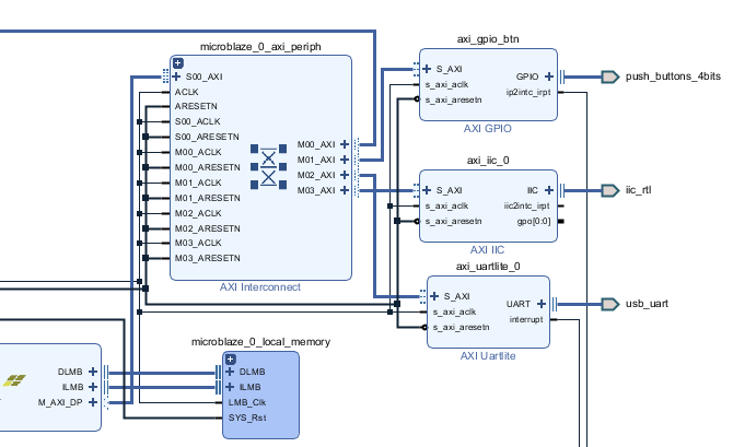
📌 Block Design
// xdc Setting //
##Pmod Header JA
set_property -dict { PACKAGE_PIN J1   IOSTANDARD LVCMOS33 } [get_ports {iic_rtl_sda_io}];#Sch name = JA1
set_property -dict { PACKAGE_PIN L2   IOSTANDARD LVCMOS33 } [get_ports {iic_rtl_scl_io}];#Sch name = JA2
📌 Main Code
typedef struct {
	XIicStats Stats;	/**< Statistics */
	UINTPTR BaseAddress;	/**< Device base address */
	int Has10BitAddr;	/**< TRUE when 10 bit addressing in design */
	int IsReady;		/**< Device is initialized and ready */
	int IsStarted;		/**< Device has been started */
	int AddrOfSlave;	/**< Slave Address writing to */

	u32 Options;		/**< Current operating options */
	u8 *SendBufferPtr;	/**< Buffer to send (state) */
	u8 *RecvBufferPtr;	/**< Buffer to receive (state) */
	u8 TxAddrMode;		/**< State of Tx Address transmission */
	int SendByteCount;	/**< Number of data bytes in buffer (state)  */
	int RecvByteCount;	/**< Number of empty bytes in buffer (state) */

	u32 BNBOnly;		/**< TRUE when BNB interrupt needs to */
				/**< call callback  */
	u8 GpOutWidth;		/**< General purpose output width */

	XIic_StatusHandler StatusHandler; /**< Status Handler */
	void *StatusCallBackRef;  /**< Callback reference for status handler */
	XIic_Handler RecvHandler; /**< Receive Handler */
	void *RecvCallBackRef;	  /**< Callback reference for Recv handler */
	XIic_Handler SendHandler; /**< Send Handler */
	void *SendCallBackRef;	  /**< Callback reference for send handler */
	int IsDynamic;		  /**< TRUE when Dynamic control is used */
	int IsSlaveSetAckOff;	  /**< TRUE when Slave has set the ACK Off */
} XIic;
위 코드는 대표적인 객체 지향 방식 코딩의 예시
함수도 주소를 가진다.
구조체와 class랑 다른 점은 구조체에서는 함수를 쓰지 못한다는 것이다.
근데 여기서 void *SendCallBackRef; 를 쓴 것을 보면,
class처럼 쓸 수 있다는 것이다.
그래서 XIic 타입을 사용해서 변수를 선언하면,
해당 구조체 내부에 있는 모든 변수나 함수를 가진 채로 선언된다.
#include <stdio.h>
#include "platform.h"
#include "xil_printf.h"
#include "xparameters.h"
#include "xiic.h"

#define IIC_ID XPAR_AXI_IIC_0_DEVICE_ID

XIic iic_device;

void lcd_init();
void lcd_send_cmd(char cmd);
void lcd_send_data(char data);
void lcd_send_string(char *str);
void lcd_put_cur(uint8_t row, uint8_t col);
void lcd_clear();

int main()
{
    init_platform();
    char buf[30];

    //--------------- Initialization ---------------//
    XIic_Initialize(&iic_device, IIC_ID); // 객체주소, Device_ID
//    XIic_Initialize(InstancePtr, DeviceId)
    u32 count=0;
    lcd_init();

    while(1){
       lcd_put_cur(0,0);
       lcd_send_string("Hello!");
       lcd_put_cur(1,0);
       sprintf(buf,"Count %-5d",count++);
       lcd_send_string(buf);
       MB_Sleep(400);
    }
    cleanup_platform();
    return 0;
}

///////////////////////////////////////////////////////////////////////////
void lcd_init()
{
   MB_Sleep(50);
   lcd_send_cmd(0x30);
   MB_Sleep(5);
   lcd_send_cmd(0x30);
   MB_Sleep(1);
   lcd_send_cmd(0x30);
   MB_Sleep(10);
   lcd_send_cmd(0x20);
   MB_Sleep(10);

   lcd_send_cmd(0x28);
   MB_Sleep(1);
   lcd_send_cmd(0x08);
   MB_Sleep(1);
   lcd_send_cmd(0x01);
   MB_Sleep(1);
   lcd_send_cmd(0x06);
   MB_Sleep(1);
   lcd_send_cmd(0x0c);
}

void lcd_send_cmd(char cmd)
{
   char data_u,data_l;
   uint8_t data_t[4];
   data_u = (cmd & 0xf0);
   data_l = ((cmd << 4) & 0xf0);
   data_t[0] = data_u | 0x0c;
   data_t[1] = data_u | 0x08;
   data_t[2] = data_l | 0x0c;
   data_t[3] = data_l | 0x08;
   XIic_Send(iic_device.BaseAddress, 0x27, data_t, 4, XIic_Stop);
}

void lcd_send_data(char data)
{
   char data_u,data_l;
   uint8_t data_t[4];
   data_u = (data & 0xf0);
   data_l = ((data << 4) & 0xf0);
   data_t[0] = data_u | 0x0d;
   data_t[1] = data_u | 0x09;
   data_t[2] = data_l | 0x0d;
   data_t[3] = data_l | 0x09;
   XIic_Send(iic_device.BaseAddress, 0x27, data_t, 4, XIic_Stop);
}

void lcd_send_string(char *str)
{
   while(*str) lcd_send_data(*str++);
}

void lcd_put_cur(int row, int col)
{
   switch(row)
   {
   case 0:
      col |= 0x80;
      break;
   case 1:
      col |= 0xc0;
      break;
   }
   lcd_send_cmd (col);
}

void lcd_clear()
{
   lcd_send_cmd(0x80);
   for(int i=0;i<70;i++)
   {
      lcd_send_data(' ');
   }
}
LCD는 두 개의 레지스터를 가진다.
명령 레지스터
- 명령이 내려지면, 그 명령을 수행한다.
데이터 레지스터
- LCD는 1열 2열 각 16자리씩 총 32개
- 메모리는 32개, 32개 총 64개 -> 64bit
메모리와 LCD의 각 자리 사이에 디코더가 하나씩 달려 있다.
왜 메모리는 64개인데, LCD는 32개인가?
17번째부터는 뒤에 있음
33번째부터 다음 줄에 출력
실제로는
ㅁㅁㅁㅁㅁㅁㅁㅁㅁㅁㅁㅁㅁㅁㅁㅁ ㅁㅁㅁㅁㅁㅁㅁㅁㅁㅁㅁㅁㅁㅁㅁㅁ
ㅁㅁㅁㅁㅁㅁㅁㅁㅁㅁㅁㅁㅁㅁㅁㅁ ㅁㅁㅁㅁㅁㅁㅁㅁㅁㅁㅁㅁㅁㅁㅁㅁ
이렇게 구성된다고 보면 된다.
우리가 가진 LCD는
0번 16 17 32
ㅁㅁㅁㅁㅁㅁㅁㅁㅁㅁㅁㅁㅁㅁㅁㅁ ㅁㅁㅁㅁㅁㅁㅁㅁㅁㅁㅁㅁㅁㅁㅁㅁ
ㅁㅁㅁㅁㅁㅁㅁㅁㅁㅁㅁㅁㅁㅁㅁㅁ ㅁㅁㅁㅁㅁㅁㅁㅁㅁㅁㅁㅁㅁㅁㅁㅁ
33 48 49 64
여기만 쓰는게 가능하도록 셋팅됨.
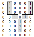
ㅁ 한 칸은 위와 같이 5x8로 구성된다.
가장 아랫줄은 커서 전용이라 비워두고 사용해야 함.
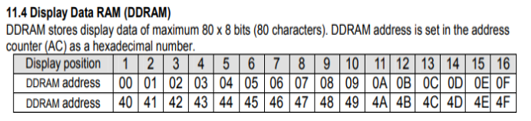
위 표는 내부에 있는 DDRAM의 주소를 나타낸 표이다.
문자를 Custom해서 사용할 수 있도록 비어 있는 메모리도 포함되어 있다.
따라서 해당 주소에 Custom한 문자를 넣어주면, 불러와서 사용할 수 있다.
LCD Custom Character Generator
Clear Invert Link
maxpromer.github.io
I2C Interface Adaptor도 두 개의 레지스터를 가진다.
얘는 시리얼 통신하는 애임(clk에 맞춰서 1bit씩 내보냄)
즉, 8bit짜리 시프트 레지스터이다.
하나 받을 때마다 1씩 카운트하는 카운터는
8bit가 다 받아지면, Set되고 LCD로 전송된다.
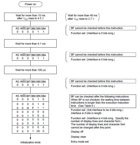
📌 Main Code - Data Sheet 기반
'
#include <stdio.h>
#include "platform.h"
#include "xil_printf.h"
#include "xparameters.h"
#include "xiic.h"

#define IIC_ID XPAR_AXI_IIC_0_DEVICE_ID

#define COMMAND 0
#define DATA 1
#define BACKLIGHT 3
#define ENABLE 2
#define RW 1
#define RS 0
#define data 1

XIic iic_device; // IIC 객체 인스턴스 선언

void Iic_LCD_write_byte(u8 tx_data, u8 rs)
{
	u8 data_t[4] = {0,}; // 핀연결 : D7 D6 D5 D4 BL EN RW RS
	 // 상위 4bit 0으로 한 번 보내고 1로 한 번 보내고,
	 // 하위 4bit 0으로 한 번 보내고 1로 한 번 보내고,
	data_t[0] = ((tx_data & 0xf0) | rs << RS | (1 << BACKLIGHT) | (1 << ENABLE));  // 첫 번쨰 보낼 데이터
	// data & 0xf0 : 상위 4bit
	// 명령일 때는 rs = 0, data일 때는 rs = 1
	// BACKLIGHT가 3번 bit이므로 3번 시프트
	// BACKLIGHT는 켤 것이면 1, 끌 것이면 0 주면 된다.
	data_t[1] = ((tx_data & 0xf0) | rs << RS | (1 << BACKLIGHT) |  (1 << RW));  // 두 번쨰 보낼 데이터
//	MB_Sleep(5); // 4.1ms Delay
	data_t[2] = ((tx_data << 4 & 0xf0) | rs << RS | (1 << BACKLIGHT) | (1 << ENABLE));  // 첫 번쨰 보낼 데이터
	data_t[3] = ((tx_data << 4 & 0xf0) | rs << RS | (1 << BACKLIGHT));  // 첫 번쨰 보낼 데이터
	XIic_Send(iic_device.BaseAddress, 0x27, data_t, 4, XIIC_STOP); // 4번 보낼 거니까 4
	return;
}

void Iic_LCD_init()
{
	MB_Sleep(15);
	Iic_LCD_write_byte(0x33, COMMAND);
	Iic_LCD_write_byte(0x32, COMMAND);
	Iic_LCD_write_byte(0x28, COMMAND);
	Iic_LCD_write_byte(0x0C, COMMAND);
	Iic_LCD_write_byte(0x06, COMMAND);
	Iic_LCD_write_byte(0x01, COMMAND); // Display Clear
	MB_Sleep(10);
	return;
}

int main()
{
    init_platform();
    char buf[30];

    //--------------- Initialization ---------------//
    XIic_Initialize(&iic_device, IIC_ID); // 객체주소, Device_ID
//    XIic_Initialize(InstancePtr, DeviceId)
//    u32 count=0;
    Iic_LCD_init();

    while(1){
//    	Iic_LCD_write_byte(0x80, COMMAND); // 0x80 : 첫 번째 줄, 0xC0 : 두 번째 줄
    	Iic_LCD_write_byte('a', data);
       MB_Sleep(400);
    }
    cleanup_platform();
    return 0;
}
int main()
{
init_platform();
char buf[30];
//--------------- Initialization ---------------//
XIic_Initialize(&iic_device, IIC_ID); // 객체주소, Device_ID
// XIic_Initialize(InstancePtr, DeviceId)
// u32 count=0;
Iic_LCD_init();
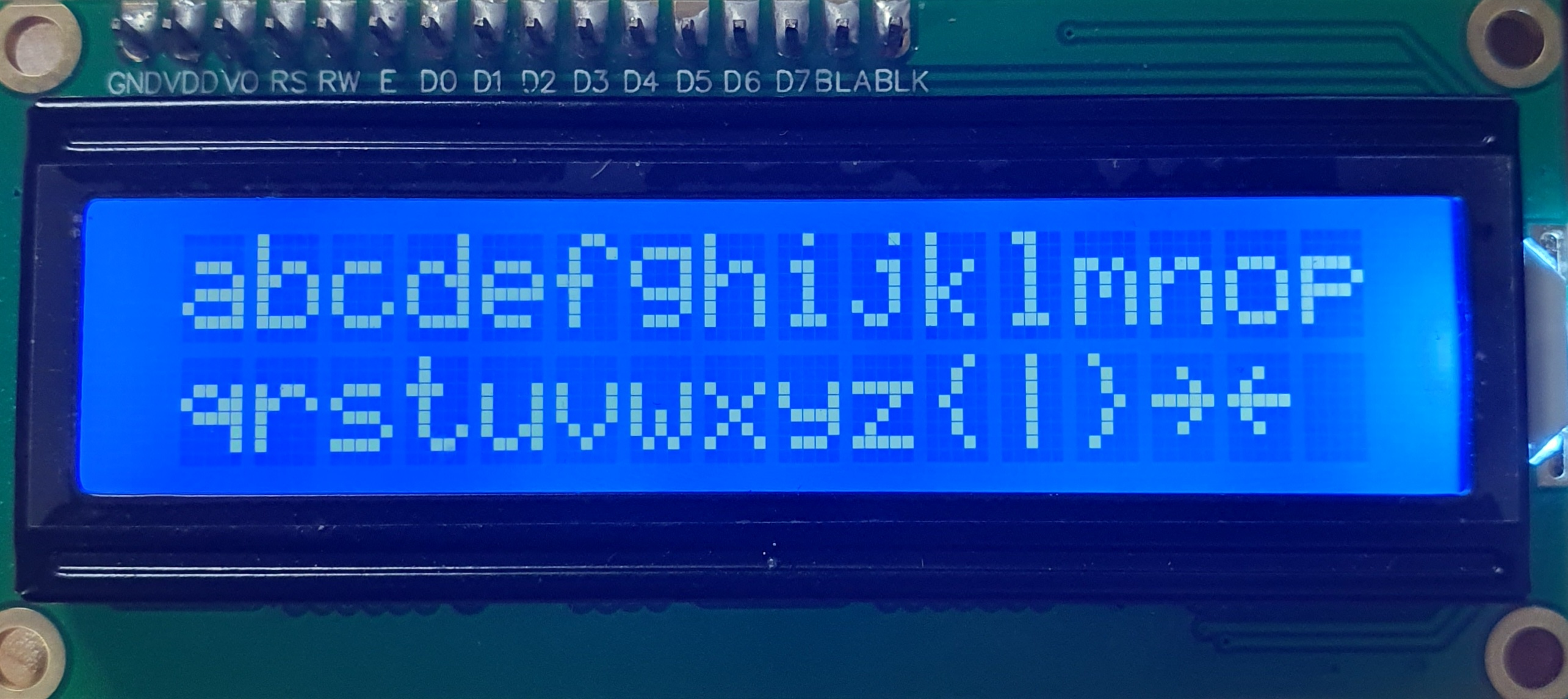
while(1){
// Iic_LCD_write_byte(0x80, COMMAND); // 0x80 : 첫 번째 줄, 0xC0 : 두 번째 줄
// Iic_LCD_write_byte('a', data);
for (int i = 0 ; i < 16 ; i++)
{
Iic_LCD_write_byte('a' + i, data);
}
Iic_LCD_write_byte(0xc0, COMMAND); // 두 번쨰 줄로 커서 옮김
for (int i = 0 ; i < 16 ; i++)
{
Iic_LCD_write_byte('q' + i, data);
}
MB_Sleep(1000);
}
cleanup_platform();
return 0;
}
커서 좌표 함수
// 커서의 좌표를 셋팅하는 함수
Iic_LCD_write_byte(0x80, COMMAND);
// 위 코드 대신 사용하기 쉽도록 함수를 따로 만들어 주자.
void Iic_gotoXY(u8 row, u8 col)
{
col %= 16;
row %= 2;
// u8 address = (0x40 * row) + col;
// u8 command = 0x80 + address;
// Iic_LCD_write_byte(command, COMMAND); // 이렇게 써도 된다.
u8 address = 0x80 | (row<<6) | col; // 6번 인덱스니까 6번 밀면 된다.
Iic_LCD_write_byte(address, COMMAND);
}
// 사용 예시 //
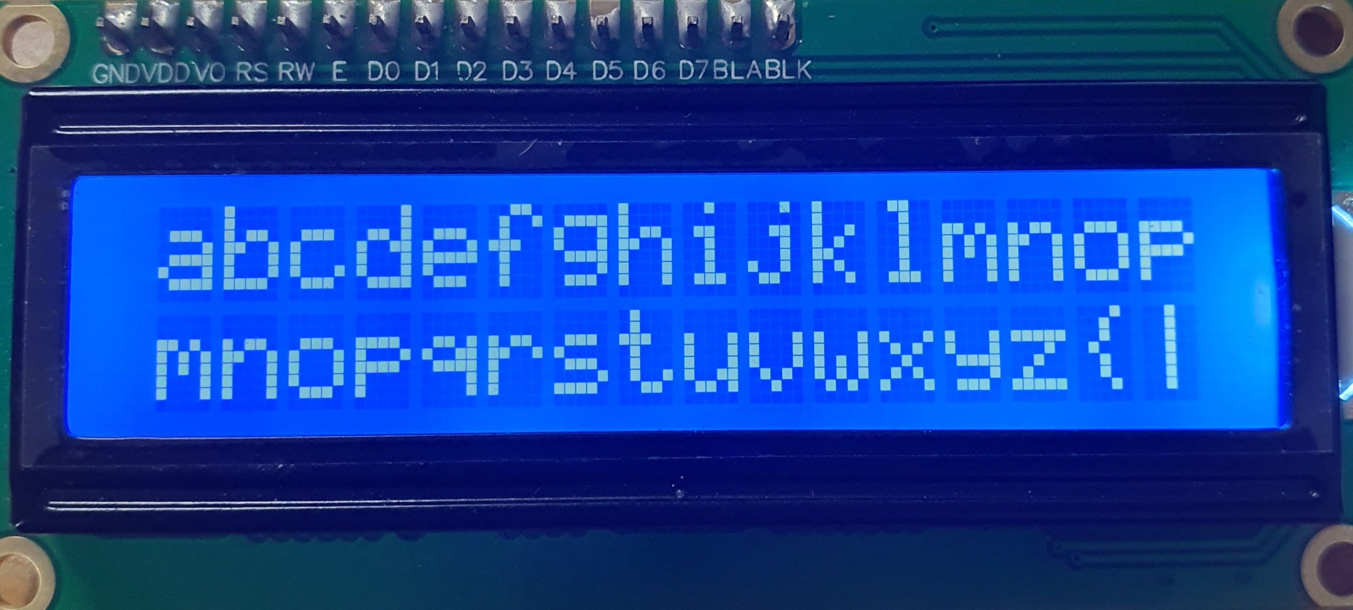
while(1){
for (int i = 0 ; i < 16 ; i++)
{
Iic_LCD_write_byte('a' + i, data);
}
Iic_gotoXY(1,0); // 두 번쨰 줄로 커서 옮김
for (int i = 0 ; i < 16 ; i++)
{
Iic_LCD_write_byte('m' + i, data);
}
MB_Sleep(1000);
}
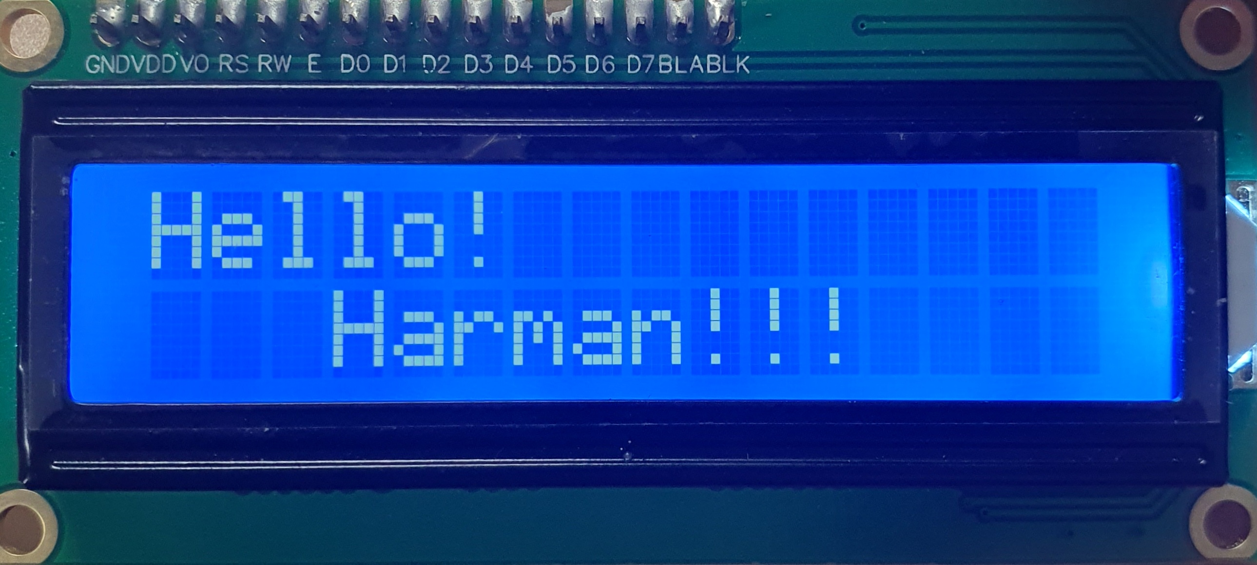
문자열 받는 함수
void Iic_writestring(char *string)
{
	for(u8 i = 0 ; string[i] ; i++)
	{
		Iic_LCD_write_byte(string[i], DATA);
	}
}

//// 사용 예시 ////
    while(1){
    	Iic_gotoXY(0,0);
    	Iic_writestring("Hello!");
    	Iic_gotoXY(1,3);
    	Iic_writestring("Harman!!!");
       MB_Sleep(1000);
    }
문자 좌시프트
int main()
{
    init_platform();
    char buf[30];
    u8 count = 0;

    //--------------- Initialization ---------------//
    XIic_Initialize(&iic_device, IIC_ID); // 객체주소, Device_ID

    Iic_LCD_init();
	Iic_gotoXY(0,0);
	Iic_writestring("Hello!!!!!asda!!!");
	Iic_gotoXY(1,0);
	Iic_writestring("Harman!!!!!!!asdaasd!!");

    while(1){
    	Iic_LCD_write_byte(0x18, COMMAND); // 한 칸씩 좌시프트하는 명령어 0x18
    	count++;
    	if(count > 15)
    	{
    		count = 0;
    		Iic_LCD_write_byte(0x02, COMMAND); // Return Home 명령어
    		MB_Sleep(2); // 리턴 홈 하기 위한 딜레이
    	}
       MB_Sleep(300);
    }
    cleanup_platform();
    return 0;
}
좌시프트 & 우시프트
int main()
{
    init_platform();
    char buf[30];
    u8 count = 0;

    //--------------- Initialization ---------------//
    XIic_Initialize(&iic_device, IIC_ID); // 객체주소, Device_ID
    Iic_LCD_init();

	Iic_gotoXY(0,0);
	Iic_writestring("0123456789ABCDEFGHIJ");
	Iic_gotoXY(1,0);
	Iic_writestring("abcdefghijk123456789");
	char left_right_flag = 1;

    while(1){
    	count++;
    	if(count > 15)
    	{
    		count = 0;
    		left_right_flag ^= 1;
    	}
    	if(left_right_flag)Iic_LCD_write_byte(0x18, COMMAND); // 좌시프트
    	else Iic_LCD_write_byte(0x1c, COMMAND); // 우시프트
       MB_Sleep(300);
    }
    cleanup_platform();
    return 0;
}
Full Code
#include <stdio.h>
#include "platform.h"
#include "xil_printf.h"
#include "xparameters.h"
#include "xiic.h"

#define IIC_ID XPAR_AXI_IIC_0_DEVICE_ID

#define COMMAND 0
#define DATA 1
#define BACKLIGHT 3
#define ENABLE 2
#define RW 1
#define RS 0
#define DATA 1

XIic iic_device; // IIC 객체 인스턴스 선언

void Iic_LCD_write_byte(u8 tx_data, u8 rs)
{
	u8 data_t[4] = {0,}; // 핀연결 : D7 D6 D5 D4 BL EN RW RS
	 // 상위 4bit 0으로 한 번 보내고 1로 한 번 보내고,
	 // 하위 4bit 0으로 한 번 보내고 1로 한 번 보내고,
	data_t[0] = ((tx_data & 0xf0) | rs << RS | (1 << BACKLIGHT) | (1 << ENABLE));  // 첫 번쨰 보낼 데이터
	// data & 0xf0 : 상위 4bit
	// 명령일 때는 rs = 0, data일 때는 rs = 1
	// BACKLIGHT가 3번 bit이므로 3번 시프트
	// BACKLIGHT는 켤 것이면 1, 끌 것이면 0 주면 된다.
	data_t[1] = ((tx_data & 0xf0) | rs << RS | (1 << BACKLIGHT) |  (1 << RW));  // 두 번쨰 보낼 데이터
//	MB_Sleep(5); // 4.1ms Delay
	data_t[2] = ((tx_data << 4 & 0xf0) | rs << RS | (1 << BACKLIGHT) | (1 << ENABLE));  // 첫 번쨰 보낼 데이터
	data_t[3] = ((tx_data << 4 & 0xf0) | rs << RS | (1 << BACKLIGHT));  // 첫 번쨰 보낼 데이터
	XIic_Send(iic_device.BaseAddress, 0x27, data_t, 4, XIIC_STOP); // 4번 보낼 거니까 4
	return;
}

void Iic_LCD_init()
{
	MB_Sleep(15);
	Iic_LCD_write_byte(0x33, COMMAND);
	Iic_LCD_write_byte(0x32, COMMAND);
	Iic_LCD_write_byte(0x28, COMMAND);
	Iic_LCD_write_byte(0x0C, COMMAND);
	Iic_LCD_write_byte(0x06, COMMAND);
	Iic_LCD_write_byte(0x01, COMMAND); // Display Clear
	MB_Sleep(10);
	return;
}

void Iic_gotoXY(u8 row, u8 col)
{
//	col %= 16;
	col %= 32; // 원래는 32까지 있으니까 이렇게 써주자.
	row %= 2;
//	u8 address = (0x40 * row) + col;
//	u8 command = 0x80 + address;
//	Iic_LCD_write_byte(command, COMMAND);
	u8 address = 0x80 | (row<<6) | col; // 6번 인덱스니까 6번 밀면 된다.
	Iic_LCD_write_byte(address, COMMAND);
}

void Iic_writestring(char *string)
{
	for(u8 i = 0 ; string[i] ; i++)
	{
		Iic_LCD_write_byte(string[i], DATA);
	}
}


int main()
{
    init_platform();
    char buf[30];
    u8 count = 0;

    //--------------- Initialization ---------------//
    XIic_Initialize(&iic_device, IIC_ID); // 객체주소, Device_ID
//    XIic_Initialize(InstancePtr, DeviceId)
//    u32 count=0;
    Iic_LCD_init();
	Iic_gotoXY(0,0);
	Iic_writestring("0123456789ABCDEFGHIJ");
	Iic_gotoXY(1,0);
	Iic_writestring("abcdefghijk123456789");
	char left_right_flag = 1;
    while(1){
//    	Iic_LCD_write_byte(0x80, COMMAND); // 0x80 : 첫 번째 줄, 0xC0 : 두 번째 줄
//    	Iic_LCD_write_byte('a', data);
//    	for (int i = 0 ; i < 16 ; i++)
//    	{
//    		Iic_LCD_write_byte('a' + i, DATA);
//    	}
//
//    	Iic_gotoXY(1,7); // 두 번쨰 줄로 커서 옮김
//    	for (int i = 0 ; i < 16 ; i++)
//    	{
//    		Iic_LCD_write_byte('m' + i, DATA);
//    	}
//    	Iic_LCD_write_byte(0x18, COMMAND); // 한 칸씩 좌시프트하는 명령어 0x18
//    	count++;
//    	if(count > 15)
//    	{
//    		count = 0;
//    		Iic_LCD_write_byte(0x02, COMMAND); // Return Home 명령어
//    		MB_Sleep(2); // 리턴 홈 하기 위한 딜레이
//    	}
    	count++;
    	if(count > 15)
    	{
    		count = 0;
    		left_right_flag ^= 1;
    	}
    	if(left_right_flag)Iic_LCD_write_byte(0x18, COMMAND);
    	else Iic_LCD_write_byte(0x1c, COMMAND);

       MB_Sleep(300);
    }
    cleanup_platform();
    return 0;
}


