728x90
[Push Button]
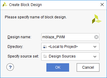
📌 Block Design
GPIO 추가

Wrapper 다시 해주고, Re-load해주면 된다.
📌 Main Code 작성
1. 하드웨어 Export 해주고
2. 플랫폼 프로젝트만들고 빌드해주고
3. 어플리케이션 프로젝트 만들고 main code 창 오픈
Push Button의 번호를 알아내기 위해 LED로 테스트해보자.
cpp
접기#include <stdio.h> #include "platform.h" #include "xil_printf.h" #include "xparameters.h" #include "xgpio.h" #define LED_ID XPAR_AXI_GPIO_LED_DEVICE_ID #define SWITCH_ID XPAR_AXI_GPIO_SWITCH_DEVICE_ID #define FND_ID XPAR_AXI_GPIO_FND_DEVICE_ID #define BTN_ID XPAR_AXI_GPIO_BUTTON_DEVICE_ID #define LED_CHANNEL 1 #define SWITCH_CHANNEL 1 #define FND_COM_CHANNEL 1 #define FND_SEG7_CHANNEL 2 #define BTN_CHANNEL 1 int main() { init_platform(); print("Start!\n\r"); /////// XGpio_Config 구조체의 주소 /////// XGpio_Config *cfg_ptr_led; XGpio_Config *cfg_ptr_switch; XGpio_Config *cfg_ptr_fnd; XGpio_Config *cfg_ptr_btn; /////// gpio 객체 /////// XGpio led_device; XGpio switch_device; XGpio fnd_device; XGpio btn_device; /////// 변수 선언 /////// u32 data = 0; u32 old_data = 0; u32 FND_data = 0; u8 fnd_value[] = {0x3f, 0x06, 0x5b, 0x4f, 0x66, 0x6d, 0x7d, 0x27, 0x7f, 0x67, 0x77, 0x7c, 0x39, 0x5e, 0x79, 0x71}; ////////////////////////////////////// Initialize Led Device ////////////////////////////////////// /////// LED /////// cfg_ptr_led = XGpio_LookupConfig(LED_ID); XGpio_CfgInitialize(&led_device, cfg_ptr_led, cfg_ptr_led->BaseAddress); XGpio_SetDataDirection(&led_device, LED_CHANNEL, 0); // 0을 줘서 출력 설정 // XGpio_CfgInitialize(InstancePtr, Config, EffectiveAddr) // XGpio_SetDataDirection(InstancePtr, Channel, DirectionMask) //-----------------------------------------------------------------------------------------------// /////// SWITCH /////// cfg_ptr_switch = XGpio_LookupConfig(SWITCH_ID); XGpio_CfgInitialize(&switch_device, cfg_ptr_switch, cfg_ptr_switch->BaseAddress); XGpio_SetDataDirection(&switch_device, SWITCH_CHANNEL, 1); // 1을 줘서 입력 설정 //-----------------------------------------------------------------------------------------------// /////// FND /////// cfg_ptr_fnd = XGpio_LookupConfig(FND_ID); XGpio_CfgInitialize(&fnd_device, cfg_ptr_fnd, cfg_ptr_fnd->BaseAddress); XGpio_SetDataDirection(&fnd_device, FND_COM_CHANNEL, 0); // 0을 줘서 출력 설정 XGpio_SetDataDirection(&fnd_device, FND_SEG7_CHANNEL, 0); // 0을 줘서 출력 설정 //-----------------------------------------------------------------------------------------------// /////// BTN /////// cfg_ptr_btn = XGpio_LookupConfig(BTN_ID); XGpio_CfgInitialize(&btn_device, cfg_ptr_btn, cfg_ptr_btn->BaseAddress); XGpio_SetDataDirection(&btn_device, BTN_CHANNEL, 0b1111); // 1을 줘서 입력 설정 /////////////////////////////////////////////////////////////////////////////////////////////////// while(1) { data = XGpio_DiscreteRead(&btn_device, BTN_CHANNEL); // 버튼 입력을 받아 XGpio_DiscreteWrite(&led_device, LED_CHANNEL, data); // 버튼에 해당하는 번호의 LED로 추력 MB_Sleep(10); } cleanup_platform(); return 0; }
Board 내 Push Button 번호
| 0 | ||
| 1 | reset | 2 |
| 3 |
[PWM]
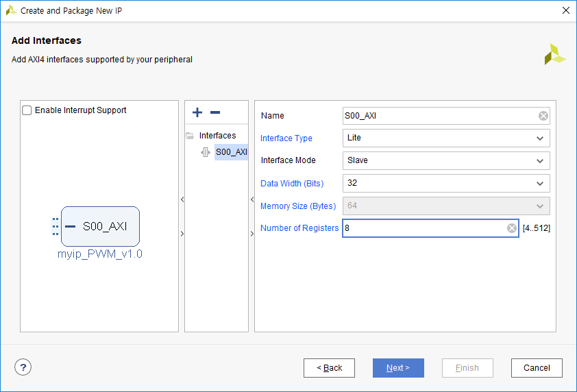
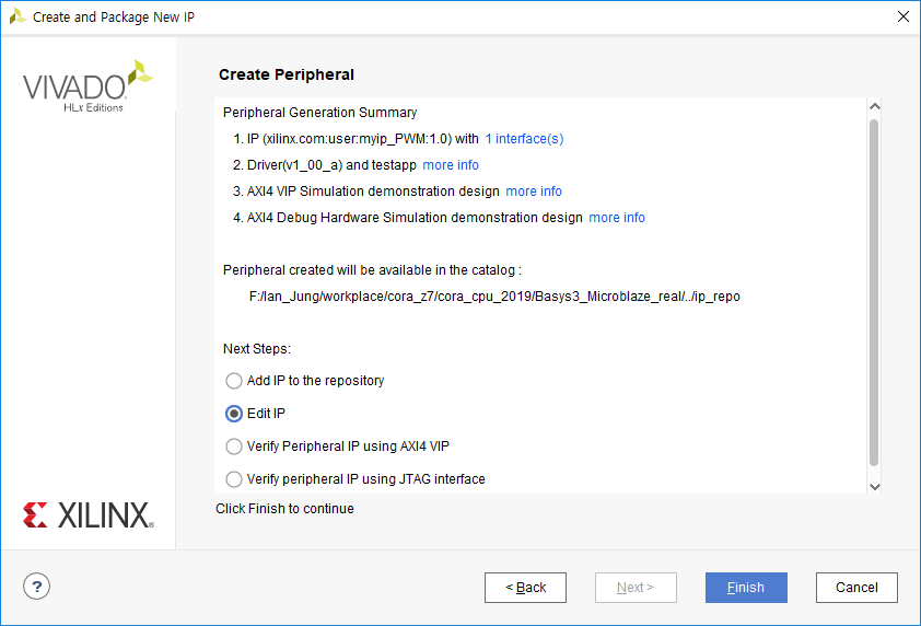
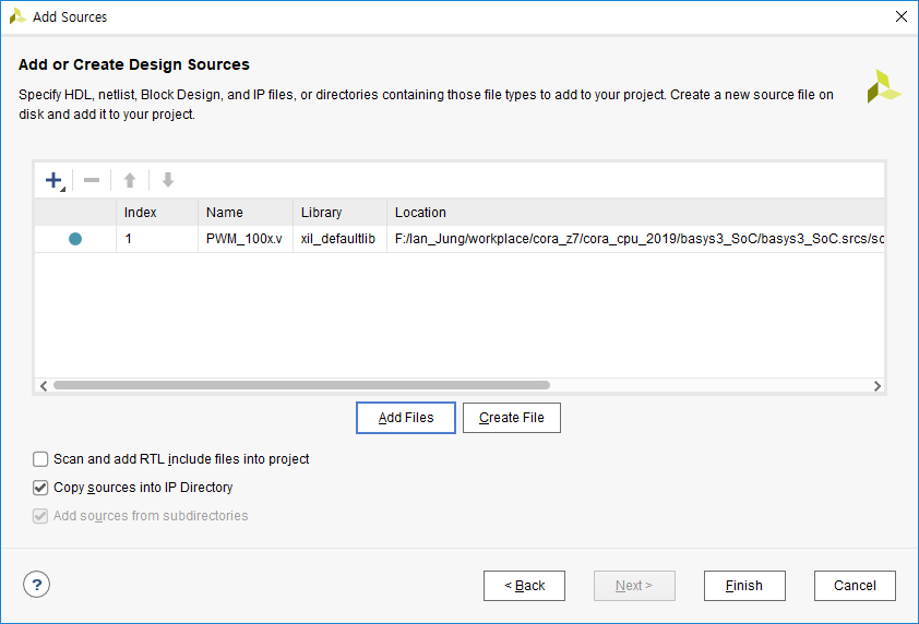
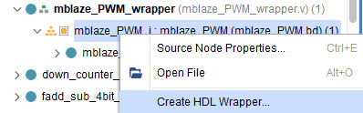
📌 Custom IP 생성
반드시 순서 지키자.
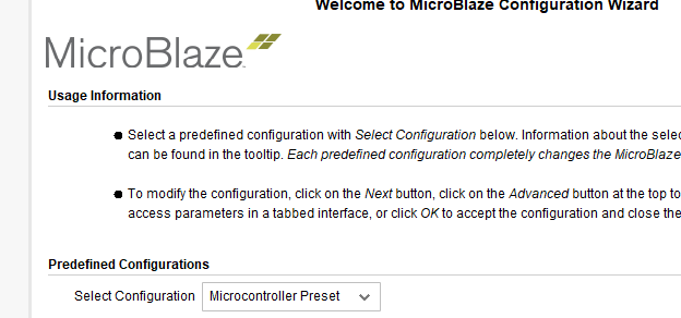
Sys clk랑 Reset 먼저 만들고 난 후, mblaze 추가해준다.
mblaze 먼저 추가해버리면, 자체적으로 clk를 만들어버리기 떄문
PWM을 활용한 LED 밝기 제어를 해보자.
cpp
접기// PWM IP 하위 모듈의 맨 아랫 줄에 추가 // // Add user logic here PWM_100 pwm100( .clk(S_AXI_ACLK), .rstp(~S_AXI_ARESETN), // reset_p이므로 비트반전한 후 넣어줘야 한다. .duty(slv_reg0[6:0]), .pwm_freq(slv_reg1), // parameter 대신 여기에 선언해도 된다. 10,000Hz 쓸 거니까 14bit .pwm_100pc(pwm_100pc) ); // pc : % -> 하나당 센티(1/100)이라는 뜻 // User logic ends // Output Port 추가 // // Users to add ports here output pwm_100pc, // User ports ends
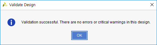
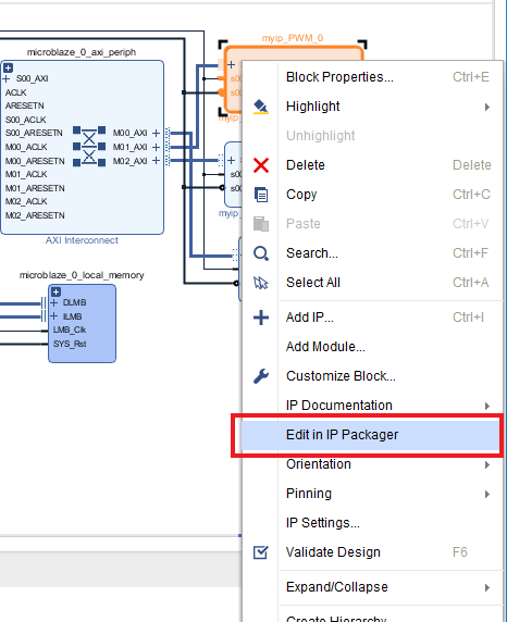
Top module에도 추가해주고 Merge/Modidy해주고 Package IP해주면, Custom IP 생성 완료
Add IP로 PWM IP를 2개 추가해주자.
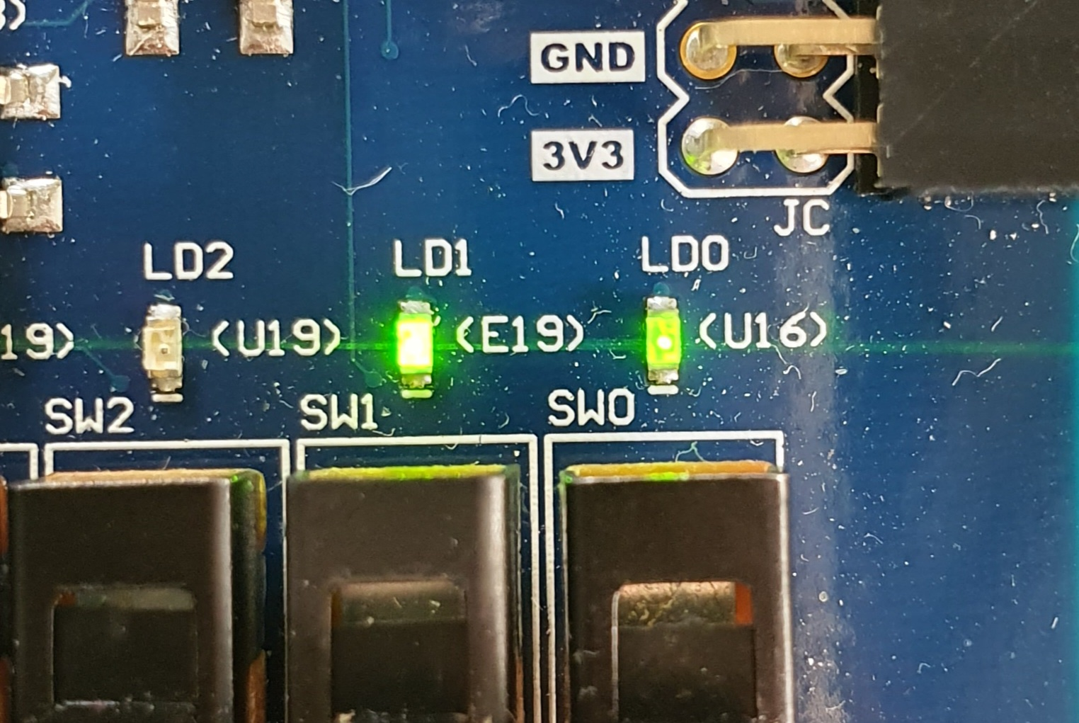
cpp
접기// xdc 파일 수정 // ## LEDs set_property -dict { PACKAGE_PIN U16 IOSTANDARD LVCMOS33 } [get_ports {pwm_100pc_0[0]}] set_property -dict { PACKAGE_PIN E19 IOSTANDARD LVCMOS33 } [get_ports {pwm_100pc_1[1]}]
📌 Main Code 작성
1. 하드웨어 Export 해주고
2. 플랫폼 프로젝트만들고 빌드해주고
3. 어플리케이션 프로젝트 만들고 main code 창 오픈
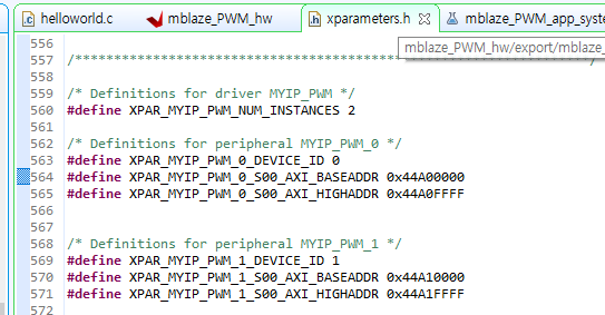
cpp
접기#include <stdio.h> #include "platform.h" #include "xil_printf.h" #include "xparameters.h" #define PWM_0_ADDR 0x44A00000 #define PWM_1_ADDR 0x44A10000 int main() { init_platform(); printf("Start!!"); volatile unsigned int *pwm_0 = (volatile unsigned int *) PWM_0_ADDR; // 32bit니까 usigned int면 충분하다. volatile unsigned int *pwm_1 = (volatile unsigned int *) PWM_1_ADDR; // 32bit니까 usigned int면 충분하다. print("debug00\n\r"); while(1) { print("Hello World\n\r"); // 배열로 접근할 수 있다. pwm_0[0] = 30; // Duty cycle pwm_0[1] = 10000; // Freq, LED 밝기 제어는 10000Hz정도 주면 된다. print("debug01\n\r"); pwm_1[0] = 90; // 배열로 접근할 수 있다. pwm_1[1] = 10000; // Freq, LED 밝기 제어는 10000Hz정도 주면 된다. MB_Sleep(1000); } cleanup_platform(); return 0; }
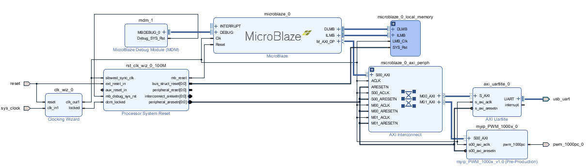
[PWM으로 Servo Motor 제어]
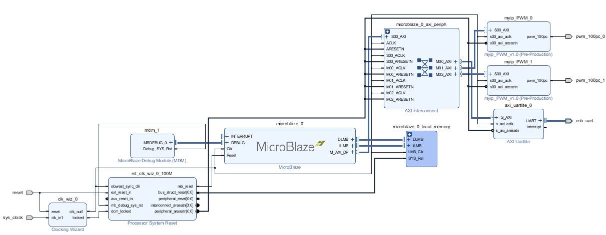
📌 Block Design 생성
PWM 1000x module을 활용한 Custon IP 생성 및 적용
📌 Main Code 작성
1. 하드웨어 Export 해주고
2. 플랫폼 프로젝트만들고 빌드해주고
3. 어플리케이션 프로젝트 만들고 main code 창 오픈
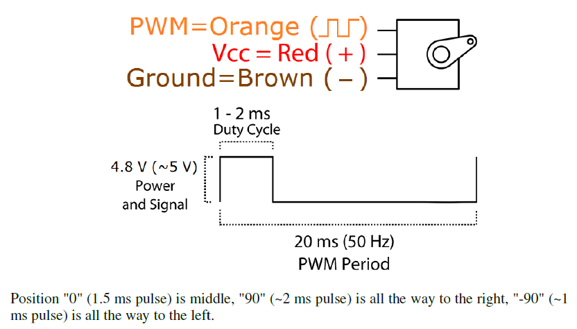
Freq : 50Hz
Duty Cycle : 5% 이내에서 조절돼야 한다.
cpp
접기#include <stdio.h> #include "platform.h" #include "xil_printf.h" #include "xparameters.h" #define PWM_0_ADDR 0x44A00000 int main() { init_platform(); printf("Start!\n\r"); volatile unsigned int *pwm_0 = (volatile unsigned int *) PWM_0_ADDR; // 32bit니까 usigned int면 충분하다. while(1) { print("90\n\r"); pwm_0[0] = 33; // Dyty pwm_0[1] = 50; // freq MB_Sleep(1000); print("0\n\r"); pwm_0[0] = 81; // Dyty pwm_0[1] = 50; // freq MB_Sleep(1000); print("-90\n\r"); pwm_0[0] = 127; // Dyty pwm_0[1] = 50; // freq MB_Sleep(1000); } cleanup_platform(); return 0; }
728x90


